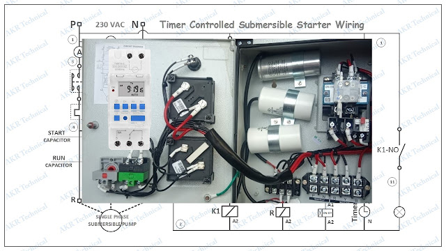
In this article contains Submersible Starter connection and control with timer switch. We will explain single phase submersible pump control panel wiring diagram. Very simple way for Dual Capacitor submersible starter connection with timer. Explains 7 x 24 Digital Timer Switch controlled wiring for single phase submersible starter.
Learn about control of Submersible starter connection and timer switch wiring. We provided link in this article for download Fully automatic Submersible Starter wiring Schematic Diagram / Drawing.
How to single-phase submersible starter and its operation. Read more, and also could download its drawing below the article.
We have explain in article single phase submersible starter and its operation, submersible starter with timer switch wiring, its hand operation and submersible starter auto operation.
We will explain in article single phase submersible starter and its operation, submersible starter with timer switch wiring, The starter hand operation and starter with timer switch automatic operation.
See below the 24 x 7 Digital Timer Switch controlled drawing and power connection for single phase submersible starter.
Click here to watch working video: working of Submersible starter
Submersible Starter Wiring Connection and its Operation
Starter getting three types for Submersible pump motor, first one is single phase single Capacitor starter and second one single phase double Capacitor starter. Third one is using three phase induction motor Direct-On-Line Starter (DOL), because its do not using starting or running capacitors. In this article we are explain single phase Double Capacitor Submersible starter with timer switch wiring connection for Submersible induction motor. All starter types can apply Timer Switch control to timely start and stop.
Single phase Submersible Starter convert into automatic starter wiring connection have two parts in the switch. First one is Hand mode and other one Auto mode. All control panels are containing these two parts.
Read more: Automatic water level controller connection with Submersible Starter
Hand Mode Wiring
To apply the timer switch first want to connect a Hand Off Auto switch between OLR NC output and stop-push button. hand position Normal Open (NO) output connect to input point of stop-push button. Now hand mode wiring complete of the submersible starter.
Auto Mode Submersible starter Wiring with Timer Switch
In auto position Normal Open (NO) output direct connect to timer switch common terminal point. The Timer coil Phase and Neutral (230 VAC) connected across to direct line voltage.
In the timer normal open contact out connected to ON delay timer A1 coil point. then this same wire looped in common contact 15 of ON delay timer. We can see in drawing, all coil A2 terminal is connected in neutral point.
See that Relay A1 connected through On-delay timer NC, The Relay marked as 'R'. The relay is only one Normal Open contact using for only 3 second switching the starting capacitor. You can see in the drawing, Relay Normal open contact 'NO' connected parallel of starting capacitor start push button open contact. So, it is only switching purpose for starting capacitor.
Submersible Starter Hand Operation
Submersible starter hand operation is start only in manual, by push 3 second in start button after start release the start button. 3 second starting capacitor serve starting torque into the motor. then continuously the motor work with Running capacitor until push the stop button.
Submersible Starter with Timer Switch Auto Operation
Auto operation of starter is simple logic with timer. In auto mode continuously the timer searches 'ON' and 'OFF' time. when reaching the 'ON' time timer 'NO' contact will close, its connected to On-Delay timer A1 point and it is energized. When energized On-delay Timer, its normal closed contact serves the supply for Relay. Therefor Relay energized and its Normal Open (NO) will be closed and Starting Capacitor will charge for 3 second. When relay get close the motor getting start torque and start the submersible pump in automatically. After 3 second motor only working with Running capacitor.
When reach 'OFF Time' in timer switch the Submersible starter will automatically off and stop pump motor.
Download diagram of Submersible Starter Timer Wiring Diagram
If you like this article share to your friends and follow this site. Learn more about electrical engineering technology.
Thanks to read this article and choose our website to know more about Submersible Starter Control wiring with Timer Switch.

