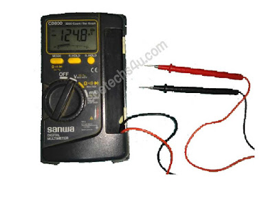
How can you use Multimeter? This article will show you how to use Digital Multimeter (DMM), is an indispensable tool. That you can use to diagnose the circuit, learn about other people's electronic designs and even a You can also test the battery. Therefore 'multi' - 'meter' (multi-measurement) name.
The most basic things we measures are Voltage and Ohms. A multimeter is also very good for some basic purity check and troubleshooting. Is your circuit not working? Does the switch work? Put the meter on it! A multimeter is your first defense while making the system problematic. In this tutorial, we will cover the measuring voltage, current, resistance, and continuity.
The selection knob allows the user to read multimeter various things like the current (A), voltage (V) and resistance (Ω) millimax (MAX).
Two investigations are plugged into two ports on the front of the unit. COM stands for mango and is almost always connected to the ground or of the circuit. The COM check is traditionally black but there is no difference between the black screen and black check except black check. 10A is the special port used during measuring large port (greater than 200mA). mAV m is the port that is plugged in a red check in a traditional way. This port allows current (up to 200mA), voltage (V), and measurement of resistance (Ω). At the end of the investigation, there is a banana type connector which plugs in the multimeter. Any probe with the banana plug will work with this meter. It allows for various types of investigation.
If you are measuring the DC voltage (such as a battery or sensor mounted for an Arduino), then you want to set the knob where there is a straight line of V. The AC voltage (such as what comes out of the wall) can be dangerous, so we rarely need to use the AC voltage settings (V with a wavy line next to it). If you are messing with AC, then we recommend that you get a non-contact examiner compared to using a digital multimeter.
Watch this video for how to use
We can also test different parts of the circuit. This study is called nodal analysis, and it is a basic building block in circuit analysis. By measuring the voltage in the circuit, we can see how much voltage is required for each component. Let's first measure the whole circuit. By measuring where the voltage is going in the resistive and then where the ground is on the LED, we should see the full voltage of the circuit, which is expected to be approximately 5V.
Then we can see how much of the LED is using the voltage. This is what is known as the voltage drop across the LED. If he does not understand now, then do not be scared. This will happen when you explore more of the electronics world. The important thing to remove is that different parts of the circuit can be measured for the analysis of the circuit.
Testing of Semiconductor Transistor
The most basic things we measures are Voltage and Ohms. A multimeter is also very good for some basic purity check and troubleshooting. Is your circuit not working? Does the switch work? Put the meter on it! A multimeter is your first defense while making the system problematic. In this tutorial, we will cover the measuring voltage, current, resistance, and continuity.
The Digital Multimeter has four parts:
- Digital Display
- Selection knob
- Probe port
- Probe
The selection knob allows the user to read multimeter various things like the current (A), voltage (V) and resistance (Ω) millimax (MAX).
Two investigations are plugged into two ports on the front of the unit. COM stands for mango and is almost always connected to the ground or of the circuit. The COM check is traditionally black but there is no difference between the black screen and black check except black check. 10A is the special port used during measuring large port (greater than 200mA). mAV m is the port that is plugged in a red check in a traditional way. This port allows current (up to 200mA), voltage (V), and measurement of resistance (Ω). At the end of the investigation, there is a banana type connector which plugs in the multimeter. Any probe with the banana plug will work with this meter. It allows for various types of investigation.
Measuring Voltage,
To begin, give the measurement voltage on the AA battery: plug the black check into the COM and red check mAVΩ. Set multimeter in "2V" DC (Direct Current) range. Almost all portable electronics use direct current), not alternating current Connect the black screen to the battery or '- and the red test to power or probe +'. Squeeze the probe with little pressure against positive and negative terminals of AA batteries. If you have got a new battery, you should see about 1.5V on the display (this battery is brand new, so its voltage is slightly more than 1.5V).If you are measuring the DC voltage (such as a battery or sensor mounted for an Arduino), then you want to set the knob where there is a straight line of V. The AC voltage (such as what comes out of the wall) can be dangerous, so we rarely need to use the AC voltage settings (V with a wavy line next to it). If you are messing with AC, then we recommend that you get a non-contact examiner compared to using a digital multimeter.
Watch this video for how to use
We can also test different parts of the circuit. This study is called nodal analysis, and it is a basic building block in circuit analysis. By measuring the voltage in the circuit, we can see how much voltage is required for each component. Let's first measure the whole circuit. By measuring where the voltage is going in the resistive and then where the ground is on the LED, we should see the full voltage of the circuit, which is expected to be approximately 5V.
Then we can see how much of the LED is using the voltage. This is what is known as the voltage drop across the LED. If he does not understand now, then do not be scared. This will happen when you explore more of the electronics world. The important thing to remove is that different parts of the circuit can be measured for the analysis of the circuit.
Warning!
In general, the DC circuits (settings on multimeter stick to straight lines, not curvy lines). The most multimeter can measure AC (alternative current) systems, but AC circuits can be dangerous. A wall outlet with AC or 'mains voltage' is the stuff that can do a great deal of you. Respect the AC very carefully. If you need to check to see if an outlet is 'on', use an AC tester. In order to measure the AC only really needs the time when we have got an outlet that is doing strange work (is it actually at 230V or 110V?), Or if we control a heater (like a hot plate) Are trying to Slow and repeat everything before testing AC circuit.Testing of Capacitor
- To test the capacitor, you can use a multimeter as an ohmmeter. Discharge the capacitor by shortening its leads. That is using a wire and connect the leads of the capacitor together. This will discharge it.
- Put your multimeter in the high ranges 10K-1M
- Connect the multymeter to capacitor leads (observe the polarity if electrolytic). As soon as the leads make contact, the meter will swing near zero. It will then move slowly toward infinity. Finally, the meter will be an infinite ohm because the capacitor is being charged by a multymeter battery.
- If the capacitor is bad, then it will go to zero ohms and will stay there. This is called a shortened capacitor.
- If the capacitor is bad, then it will go to zero ohms and will stay there. This is a shortened capacitor Called.
- In the case of an open capacitor, there will be no ohmmeter signal or indication.
- Some capacitors have low dielectric leakage. You will know whether the ohmmeter rests at a lower point than infinity. To make sure to test the same kind of good capacitor
Testing of Semiconductor Diode,
- Using the multymeter, the Voltage across the diode is measured.
- Keep multimeter in diode range (diode symbol is given).
- Touch positive probe of a multymeter to the Diode anode and negative probe to the cathode. (Forward bias)
- It will show some value between 0.5v to 0.7v (Low Voltage).
- By altering connection (Reverse Bias) it will show infinite Voltage (1. ON multymeter display)
- Then the diode is OK, otherwise faulty.
Testing of Semiconductor Transistor
- First identify the leads of the transistor
- Using the multymeter, Voltage across the transistor leads are measured
Testing of LED (Light Emitting Diode)
- LED (Light Emitting Diode) has two leads. A small one is a cathode & large one is the anode.
- To check, keep multimeter knob on in resistance range and select Diode symbol in selection switch.
- Forward bias (+ to +), the LED will glow.
- In reverse bias(- to +), it will not glow. Then LED is ok.


