The transformer is an electrical device in which there are two or more coils of wire. That is used to transfer electrical energy through a changing magnetic field.
A single-stage transformer can work to increase or decrease the applied voltage on the primary rotation. When a transformer is used to increase the voltage on its secondary rotation in relation to the primary. So it is called step-up transformers. When it is used to reduce the voltage on the secondary rotation in relation to primary, it is called step-down transformers.
Compared to the number of coils on the secondary winding (Ns), the voltage difference between primary and secondary windings is obtained by changing the number of coils in the primary winding (Np).
The transformer ratio changes
Note that while converting a transformer the sequence ratio of numbers changes as the ratio. The ratio of the turn 3: 1 expresses a very different transformer relationship and output voltage, from which the turn ratio of one is given as 1: 3.
Transformers Basics Example Number 1
One voltage transformer has 1500 turns of wire on the primary coil and its secondary turns have 500 turns of wire. What will be the turn ratio of the transformer?
This ratio of 3: 1 (3-to-1) simply means that there are three primary windings for each secondary curve. Since the ratio runs to a small number from the left side to a small number. The primary voltage goes down in the shown value.
Transformers Basics Example Number 2
If 240 Volts RMS is applied to the primary rotation of the same transformer, what will be the resultant secondary no-load voltage?
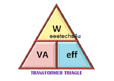
And by transferring the above triangles, we get the following combination of the equation:
To find Watts (output) = VA x eff
VA (input) = W ÷ eff
Efficiency, find eff = W ÷ VA
Eddy current loss
The Transformer eddy current on the other side is caused by the flow of the flow of induced currents in the steel due to the flow of magnetic flux around the current loss core. These circulation currents arise because the core for magnetic flux is acting like a loop of wire. The eddy currents induced by a solid iron core will be large because the iron core is a good conductor.
Eddie currents do not contribute to the utility of Transformer, but rather they resist the flow of induced flow by acting like a negative force producing resistant heating and the loss of electricity within the core.
A single-stage transformer can work to increase or decrease the applied voltage on the primary rotation. When a transformer is used to increase the voltage on its secondary rotation in relation to the primary. So it is called step-up transformers. When it is used to reduce the voltage on the secondary rotation in relation to primary, it is called step-down transformers.
 |
| Transformer Basics and Calculations |
Compared to the number of coils on the secondary winding (Ns), the voltage difference between primary and secondary windings is obtained by changing the number of coils in the primary winding (Np).
The transformer ratio changes
Note that while converting a transformer the sequence ratio of numbers changes as the ratio. The ratio of the turn 3: 1 expresses a very different transformer relationship and output voltage, from which the turn ratio of one is given as 1: 3.
Transformers Basics Example Number 1
One voltage transformer has 1500 turns of wire on the primary coil and its secondary turns have 500 turns of wire. What will be the turn ratio of the transformer?This ratio of 3: 1 (3-to-1) simply means that there are three primary windings for each secondary curve. Since the ratio runs to a small number from the left side to a small number. The primary voltage goes down in the shown value.
Transformers Basics Example Number 2
If 240 Volts RMS is applied to the primary rotation of the same transformer, what will be the resultant secondary no-load voltage?And by transferring the above triangles, we get the following combination of the equation:
To find Watts (output) = VA x eff
VA (input) = W ÷ eff
Efficiency, find eff = W ÷ VA
Transformer Triangle image
 |
| Transformer Basics and Calculations |
Eddy current loss
The Transformer eddy current on the other side is caused by the flow of the flow of induced currents in the steel due to the flow of magnetic flux around the current loss core. These circulation currents arise because the core for magnetic flux is acting like a loop of wire. The eddy currents induced by a solid iron core will be large because the iron core is a good conductor.
Eddie currents do not contribute to the utility of Transformer, but rather they resist the flow of induced flow by acting like a negative force producing resistant heating and the loss of electricity within the core.


