An Automatic Transfer Switch (ATS) is an electrical switch that switches a load between two Electrical power sources. An Automatic Transfer Switch (ATS) panels will be designed to automatically changeover from mains Power supply to standby generators. If the failure of the mains supply the Generator supply will restore in the system.
The Automatic Transfer Switch (ATS) or Auto Change Over Switch will automatically change back to normal supply. But do not stops the generator automatically. When manually stop the Engine, then standby generator is shut down after a cooling down period. If the main power source will stop working or fails to deliver the required load, manually start generator.
The Load will automatically transfer to the generator through ATS panel. Two types of Transfer Switch are using in between main power, Generator power supply and Inverter power for Home and other utility.
2, Automatic Transfer Switch (ATS)
An Automatic Transfer Switch (ATS) will often installed where a backup generator is located. The Generator will provide temporary Electrical power if the main source fails.
The ATS control panel’s function will detect a power failure and automatically transfer the load to the generator. So the working of the control panel will detection of voltage drop and failure of the normal source of power.
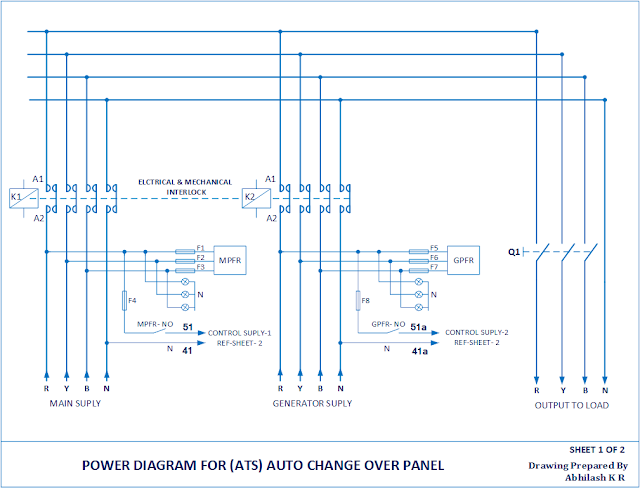
So generally Power Failure Relay ( PFR ) will monitor all phases at all time. This name will be mentioned in the Automatic Transfer Switch (ATS) Power diagram. Therefore Failure points or Under Voltage Relay (UVR) will be defined as the voltage drop in any phase.
Normal supply healthy,
The Auxiliary contactor or Relay (both are using for control system) ‘KX1’ get energized during main supply is the healthy condition.
It will feds Control supply-1 through Main Power Failure Relay Normal Open (MPFR-NO) contacts. The Control supply-2 from Generator Power Failure Relay-Normal Open (GPFR-NO) is open due to open contacts of KX1 auxiliary Contactor or Relay.
NO = Normal Open contact.
NC = Normal Close contact.
Normal supply fails,
The Auxiliary contactor or Relay (both are using for control system) ‘KX1’ get de-energized during the main supply fails condition.
It will get control supply via ‘KX1’ NC Contacts (Normal Close) to control supply phase and neutral, if Generator is running condition.
Automatic Transfer Switch (ATS) control diagram
 |
| Automatic Transfer Switch (ATS) |
How to Work an Automatic Transfer Switch (ATS)
The Automatic Transfer Switch (ATS) or Auto Change Over Switch will automatically change back to normal supply. But do not stops the generator automatically. When manually stop the Engine, then standby generator is shut down after a cooling down period. If the main power source will stop working or fails to deliver the required load, manually start generator.
The Load will automatically transfer to the generator through ATS panel. Two types of Transfer Switch are using in between main power, Generator power supply and Inverter power for Home and other utility.
1, Manual change over switches,
Manual change over switches is using for backup in between Main power, Generator power, and Inverters. Manual transfer switches will use in normal situations. Usually at homes small offices and shops.2, Automatic Transfer Switch (ATS)
An Automatic Transfer Switch (ATS) will often installed where a backup generator is located. The Generator will provide temporary Electrical power if the main source fails.
Working Principle of Auto Transfer Switch (ATS)
The ATS control panel’s function will detect a power failure and automatically transfer the load to the generator. So the working of the control panel will detection of voltage drop and failure of the normal source of power.
So generally Power Failure Relay ( PFR ) will monitor all phases at all time. This name will be mentioned in the Automatic Transfer Switch (ATS) Power diagram. Therefore Failure points or Under Voltage Relay (UVR) will be defined as the voltage drop in any phase.
Power Failure Relay (PFR) Functions
PFR is a main part of automatic transfer switch. Most of Power Failure Relay (PFR) always monitoring phase sequence in three phase supply. So, in case change the R,Y and B sequence the relay will fail and stop the control supply output. The other advantage, stops output control supply in case one or two phase fail the three phase supply. In this device can set lower and upper limit and delay time of line voltage. So, It use as an important part of control system.
Automatic Transfer Switch (ATS) Power connection,
 |
| Automatic Transfer Switch (ATS) power connection |
Normal supply healthy,
The Auxiliary contactor or Relay (both are using for control system) ‘KX1’ get energized during main supply is the healthy condition.
It will feds Control supply-1 through Main Power Failure Relay Normal Open (MPFR-NO) contacts. The Control supply-2 from Generator Power Failure Relay-Normal Open (GPFR-NO) is open due to open contacts of KX1 auxiliary Contactor or Relay.
NO = Normal Open contact.
NC = Normal Close contact.
Normal supply fails,
The Auxiliary contactor or Relay (both are using for control system) ‘KX1’ get de-energized during the main supply fails condition.
It will get control supply via ‘KX1’ NC Contacts (Normal Close) to control supply phase and neutral, if Generator is running condition.
The disadvantage of Automatic Transfer Switch (ATS),
Finally the disadvantage of fully auto Automatic Transfer Switch (ATS). That in case of any failure of the whole system and will stop working. So maybe any time auto/manual ATS panel system failure. That time handle the system you can manually in case of any failure.If you like this article share to your friends and follow this site. Learn more about electrical engineering technology.
Thanks to read this article and choose our website to know more about Automatic Transfer Switch (ATS) working.
